Introduction
Although Lidars are getting cheaper these days, 3D lidar can still cost >$4000 such as VLP-16. An alternative approach is to create a 3D lidar by rotating 2D lidar such as mentioned in this article that is using Hokuyo 2D lidar that is still quite expensive and cost a few thousand bucks.
This article introduces a DIY 3D Lidar made with an extremely low-cost 2D Lidar, a servo motor and a few 3D printed parts with a total cost around $100. The performance is verified by performing 3D mapping using the LOAM software.
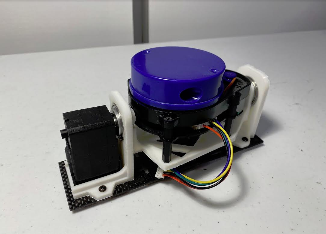
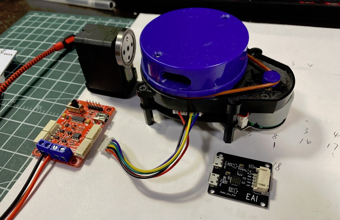
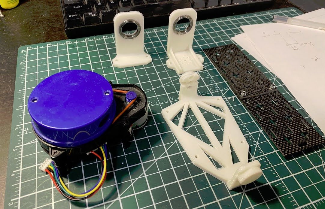
Hardware
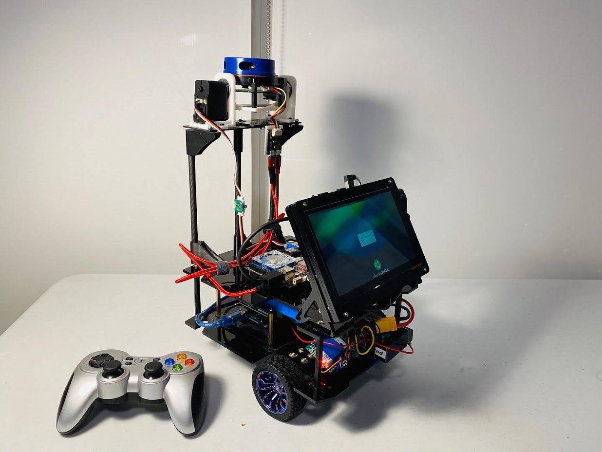
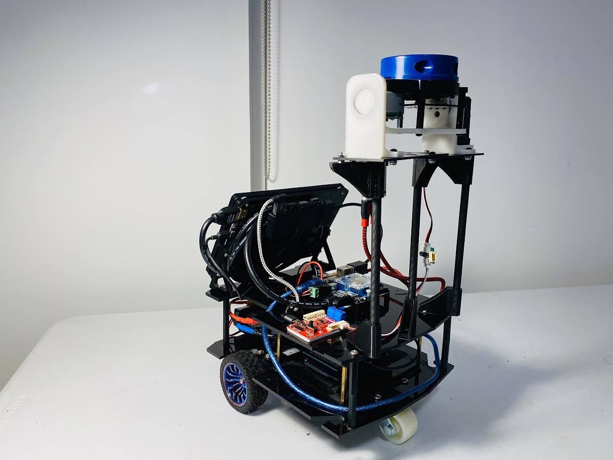
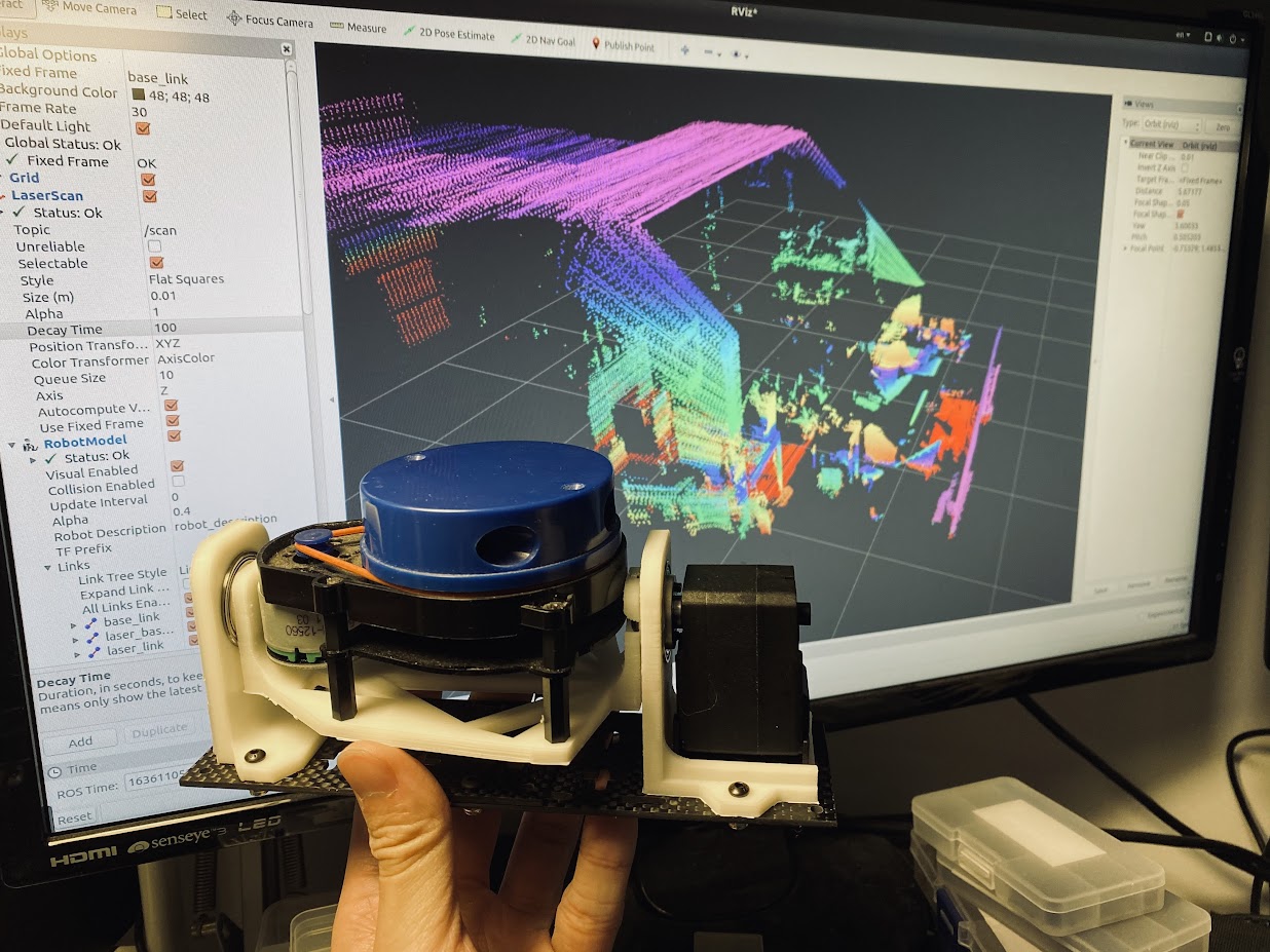
The overall hardware is quite simple. It includes a YDlidar X4, a Feetech STS3215 serial bus servo, some bearings and 3D printed parts.
The good thing about using this serial bus servo instead of a regular PWM driven hobby servo is that I can easily control the speed and obtain angle feedback that makes the software implementations easy.
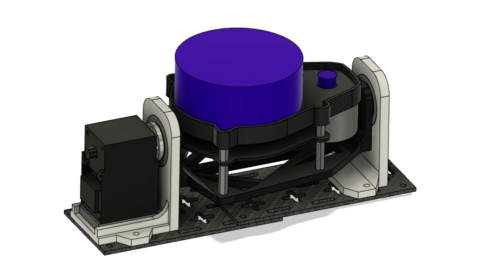
I also made a mount to attach it to a mobile platform that has two wheels with encoders and an onboard computer so that I can test 3D mapping softwares with it.
Software
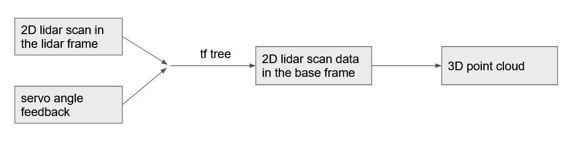
ROS is used in the software here. Firstly I need to make a Tf tree that includes the information of the relative pose of the lidar scan data to the base. Here’s a simplified Tf tree digram of the system.

Once the Tf tree is created, then I just need to publish the 2D lidar scan in the corresponding frame. Then the laser_geometry package is used here to convert the 2D lidar scan data to the point cloud data format, so that the data can be fed into popular 3D mapping softwares.
Videos
This video shows the point cloud rendering in Rviz. Note that this is not really “mapping”. I simply added data display delays of all the lidar scan data and it accumulated over time. Wheel odometry was also used in the demo with the mobile platform.
This video shows the actual 3D mapping with the LOAM software that was originally created by Ji Zhang et al. back in 2014. I needed to make a few adaption to the software to get it work properly. The original software used some calculation to determine whether a sweep is done (lidar rotating from one end to the other end) while my data is too sparse to do that, so I modified the software to receive an empty message published from my diy 3dlidiar ROS node to determine whether a sweep is done.
Conclusion
Overall the project is quite successful and achieved basic indoor 3D mapping. There are two major drawbacks of the system:
* firstly the scan frequency is too low (around 10hz for 2D scan) since it is using a very low-cost 2D lidar
* secondly there’s no correction for the 2D lidar data distortion (ideally this can be done with an IMU mounted on the lidar) that I needed to move the robot very slowly to map properly
Awesome, thanks for sharing!